
Blog Index

Introducing GBSCSI

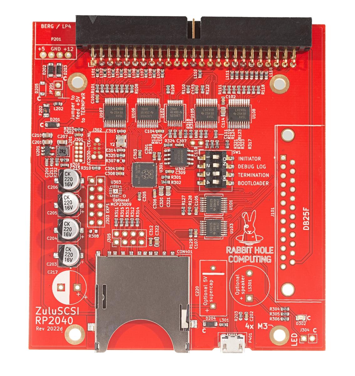
We sell quite a few of our ZuluSCSI offerings. However, we've heard your requests: you want a more affordable option. Maybe you don't use your vintage computer that often. Or, maybe you're on a tight budget. (We certainly are!)

To that end, we're now carrying the GBSCSI2 OSHW SCSI drive emulator. We'll continue to carry the ZuluSCSI, and both boards use the same great firmware with the ZuluSCSI project's approval.

We asked the board's designer, George Mezzomo, to talk a bit about designing the GBSCSI.

A top-down photo of the GBSCSI 3.5" Hybrid.

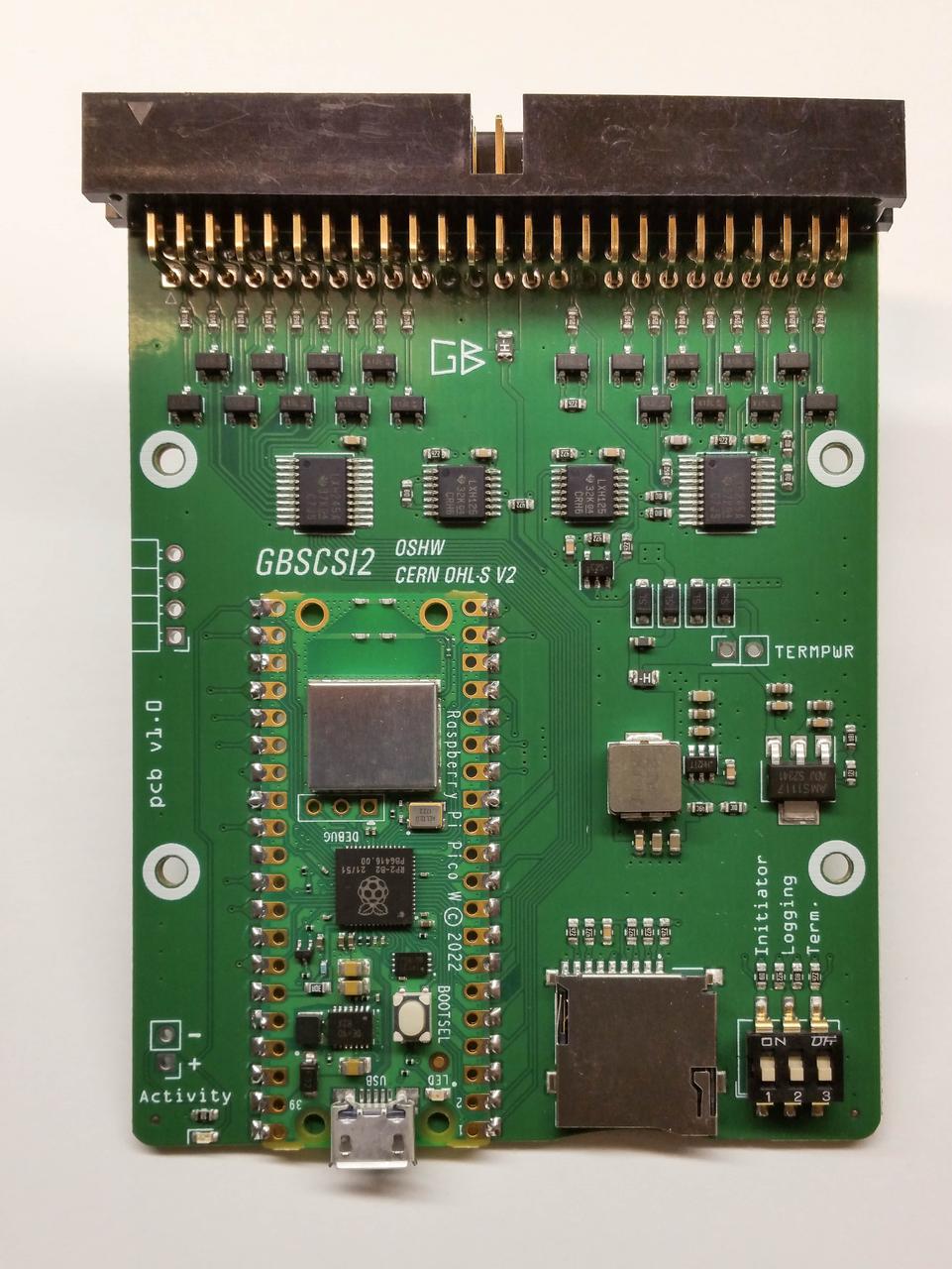
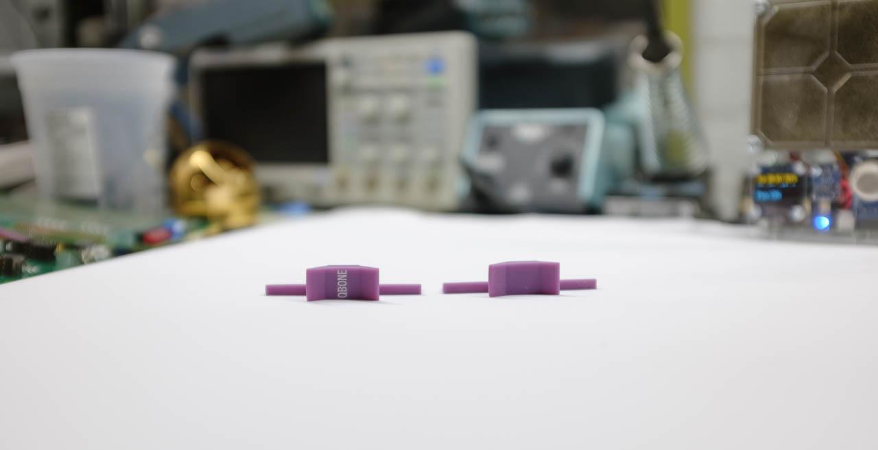
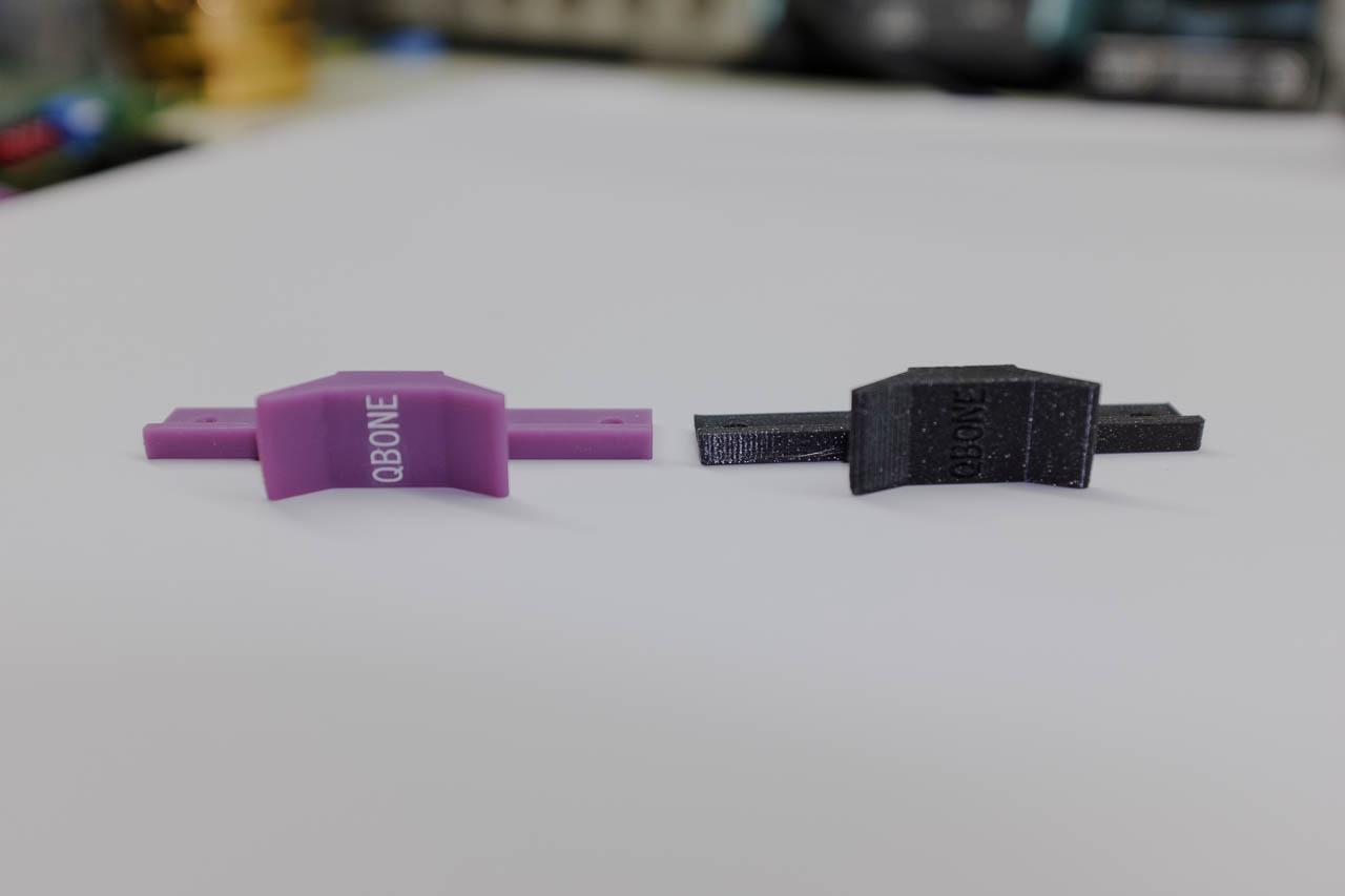
The GBSCSI 3.5" Hybrid.

Tell us a bit about yourself, George.

I started with disassembling my toys at an early age, learning how things worked, moved on to collecting computers at age 10, and then all sorts of odd stuff, anything I could buy cheap and fix to satisfy my curiosity. At some point in my early life I started doing my own PCBs with sharpie and ferrochloride, copying designs from 80s magazines, and later tried designing boards, but wasn't much good at it (due to not knowing how to use the software properly). I then went to college to become an EE (where PCB design surprisingly isn't really taught). I was dissatisfied with school and had recently lost my dad, so I really needed something to occupy myself with. A colleague (and good friend) taught me the basics of EDA, and I liked doing that so much I've decided that's what I want to do for a job.

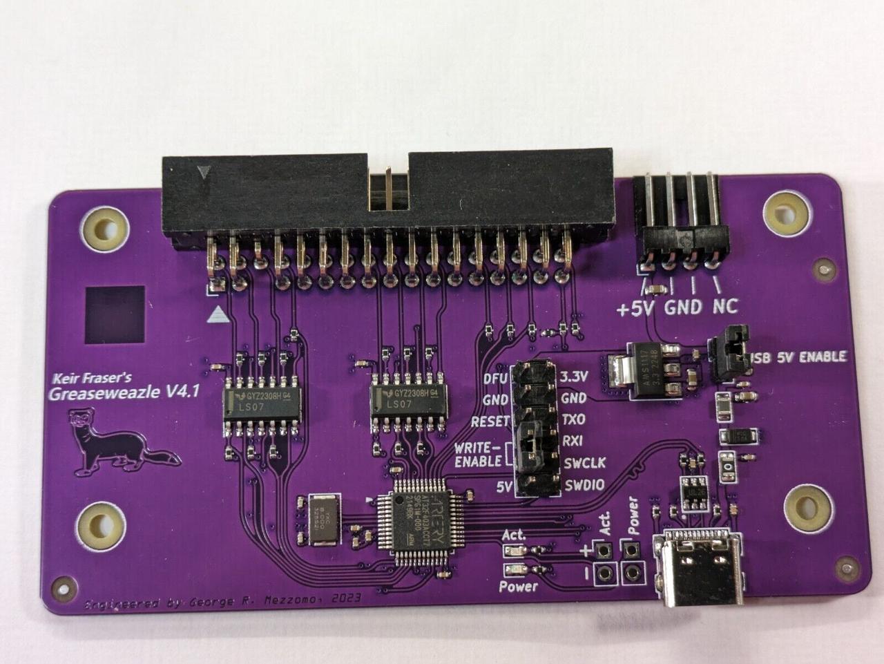
You're the PCB designer for the Greaseweazle. How did you get involved in that project?

I had bought an Amiga 600 for peanuts, but writing disks for the Amiga from a PC involved using a parallel port cable and DOS software - clunky, from a laptop, and results were also often unreadable. Then Greaseweazle appeared, and made that much easier and convenient - I could just use a cheap Bluepill board and a USB port, from within Windows or Linux. However, STM32 fakes flooded the market, and buying a Bluepill that would work with Greaseweazle became almost impossible. I decided I could use my newly-acquired PCB design skills to create a board that bypassed the need for the Bluepill+adapter, one that would have a STM32 from a known-good source fitted to it from the factory. Then this got moved to a higher-performance variant, and, when STM32 parts became scarce during the post-pandemic supply chain crisis, the design got yet again remade to use an improved clone chip. This has now been polished and refactored into v4.1.

A picture of the Greaseweazle v4.1.

The Greasewewazle v4.1 USB-floppy interface.

Why make the GBSCSI ?

GBSCSI sort of appeared from the same pattern as the Greaseweazle: I wanted a cheap device - in this case, one I could order preassembled in bulk to fit all my machines that needed their failing storage replaced (and there were many of them). STM32 CPUs were impossible to buy, and people were charging insane prices for Bluepills, fake or otherwise. Thus, an ArdSCSIno-stm32 compatible PCB was lashed-up, and released as the original GBSCSI. It originally used the cheapest clone chip I could find, which wasn't very good.

This was just cheap, devoid of any polish, but fulfilled my initial needs. However, SCSI Disk Emulators have since progressed. Since I'm lazy, and a terrible programmer, I don't want to maintain my own firmware, but I like having hardware tailored to my needs. GBSCSI2 was originally going to be a buffered variant of the earlier board, also STM32 (or similar), but given the performance increase offered by devices based on the RP2040, the decision was made to target compatibility with those.

What makes the GBSCSI different?

I wanted a design that could fit all my machines, regardless of whether they used 2.5" or 3.5" disks, with a single PCB design. Ordering 25 identical boards is much more economically efficient than ordering 10 of one design, and 15 of the other. This was the original aim of the design. Other than that, it's mostly personal preference - where I want my connectors and switches placed, that sort of thing. If I make my own board, I am afforded the freedom to change those to what I consider most convenient for my use, but also what friends I talked to would want.

Any other interesting projects coming up?

I have been meaning to refresh a few old designs and get them out the door - maybe they'll get released for public consumption, once I test them. You can see my older designs on GitHub. The real fun stuff is under NDA!

Thanks again, George, for taking the time to speak with us!


Introducing ZuluSCSI


2022-11-05 Update: As of today, we've blown through our initial ZuluSCSI v1.1 supply, and now stock the updated ZuluSCSI RP2040 design. These new devices support synchronous transfer, which means read speeds have been measured up to 9.5MB/s with suitable host hardware. Yet another win for the ZuluSCSI development team! We're thrilled to be offering these for sale as of today.

Our original blog post about the ZuluSCSI is below. For more info on the history of the ZuluSCSI product line, see the manufacturer's FAQ.


The global electronics parts shortage has not spared DECromancer. Back in April of 2022, we sold the last of our SCSI2SD v5.2 stock. Despite high demand, we've not been able to meet your needs - until now.

Shortly after we ran out of stock, Rabbit Hole Computing quietly launched ZuluSCSI, a port of their SCSI2SD v6 code to the GigaDevice GD32F205 ARM processor. We watched the project with great interest. It claimed better performance than the old SCSI2SD v5.2, and has a much easier-to-use configuration: no more app, just edit the ZuluSCSI.ini file on your SD card and copy your disk or CD-ROM ISO images to the file!

A top-down photo of the ZuluSCSI RP2040.

The ZuluSCSI RP2040.

But we didn't want to start carrying the product until we were sure it would work for the vintage machines we support. The first good news came when Chicken Systems founder Garth Hjelte roundly endorsed the ZuluSCSI's compatibility with samplers:

ZuluSCSI works with EVERY SINGLE SAMPLER we know of (which is all of them). All Ensoniq, Akai, Akai MPC, Roland, Emu, Ensoniq, Kurzweil, Korg, Peavey, Synclavier, Fairlight, Waveframe samplers. We don't provide a list because we haven't found a sampler it DOESN'T work on.

Plus, we knew the STM32-based SCSI2SD v6 worked well in all sorts of vintage computers, including our own collection. Things were looking up. But it was time to put the ZuluSCSI to a torture test.

After chasing our tails for an hour over a bad 50-pin SCSI cable, we found the ZuluSCSI worked flawlessly in a DEC PDP-11/23 (with CMD CQD-220 controller), an original NeXT Cube (NCR 53C90-based), and even the oddball WICAT S2150.

A picture of the ZuluSCSI (v1.1) running inside our WICAT S2150, connected to a DEC VT240 with colour VR241 monitor.

The ZuluSCSI running inside our WICAT S2150 (and DEC VT240 terminal).

We're very pleased with the performance and ease-of-use, and are proud to open sales up through our web store.


Some quick tips from our experiences:

  • Use a FAT32-formatted SD card with a single, primary partition.

  • For a single hard drive, place your file on the card, named HD0.img.

  • For a CDROM image, use the name CD4.iso for SCSI ID 4.

  • Our WICAT needs 1024-byte sectors. Just rename the file HD00_1024.img to make it work. (The first zero is the SCSI ID, the second is the LUN.)

  • If you need any special options, copy the zuluscsi.ini file onto your SD card and edit.

  • For very long SCSI cables, or machines without SCSI terminator power, you may need to add a 4-pin Berg ("floppy") power header to the board. You can also add a jumper to let the ZuluSCSI drive power SCSI termination on the cable if you like. (We'll offer adding these headers to the boards for you prior to shipping in the near future.)


Calibrating the MFM Emulator's voltage sensor

Recently, we had a customer complain that their MFM Emulator would get stuck in a boot loop whenever they enabled automatic startup of emulation on boot (as you might like to do when permanently installing the MFM Emulator in an old computer). We've been scratching our heads as to what might have gone wrong - and finally reproduced the issue in our lab. It turned out that wo issues were at fault here:

  1. Our most recent units (S/N 070 and newer) have a slight resistor value change, and

  2. This particular customer's 12V line in their vintage computer was sagging at 11.6V.


When enabling the MFM Emulator's "start emulating on boot" functionality, the powerfail program is started in the background. powerfail monitors the 12V line to see if it drops below 11.5V. If so, the program exits emulation and forces a shutdown, syncing all data to the flash/USB drives attached.

The BeagleBone senses the 12V line through a simple resistor divider, divided down to about 1.4V because the BeagleBone's analog-to-digital converter can accept a maximum of 1.8V. However, in the lab, the latest unit out of assembly read the 12.00V line at 11.6V! Because of the small resistor values used, a difference of just 20 ohms accounts for this major variation in sensitivity. And for our unfortunate customer, 11.6V read 0.4V low would be well below the 11.5V threshold, forcing a reboot - and ending up in a boot loop.

The change of resistor value was forced by the global supply chain shortage in components, meaning we were unable to source one particular resistor. Unfortunately, this resistor acts as a divider on the 12V line, feeding the analog-to-digital converter on the BeagleBone, which is used to detect a power failure situation.

The great news is that users of the MFM Emulator can fix this themselves in software. Simply edit the file /etc/mfm_emu.conf and change the line

PowerFailOptions=""

to

PowerFailOptions="--scale 0.1213"

We've updated the pack-in letter to call out this change for anyone who may need it.

If you want to fully calibrate your unit's voltage measurement, you'll need a voltmeter. Here's how:

  1. Power the MFM Emulator via the 4-pin Molex connector, and ssh to your MFM emulator as root.

  2. Run the following commands:

    echo cape-bone-iio > /sys/devices/bone_capemgr.*/slots

    cd ~/powerfail

    ./powerfail --debug --powercmd true --threshold 0 --scale 0.1253

  3. With your voltmeter, measure the voltage at the P3 (!2V) test point on the emulator.

  4. If the printed value does not match within 0.02V of the measured value, adjust the scale value. Decreasing the scale value will increase the value measured by powerfail.

Thanks to our customer for helping us debug this issue.


QBone Part 7: Yukon Gold

Some of you noticed the easter egg in our last blog post: the yellow QBone shown in the final image gallery.

Oho, what's this?

Back when we first opened our web store, selling Snark Barkers, we received a common request: "are the edge connectors on these hard gold?" For the Snark Barker, and for the regular QBone, the answer is: no, they're ENIG.

ENIG deposits a very thin layer of gold via an immersion process over the top of the standard electroless nickel plating. The gold layer's thickness varies from 0.05 - 0.23 µm, over a 2.5 - 5.0 µm thick electroless nickel layer. We like ENIG for our boards, for many reasons:

  • Excellent resistance to oxidation

  • Low contact resistance and high strength

  • Good through-hole plating.

  • Surface finish is ideal for fine-pitch ICs, as it keeps the pads square-edged and flat.

  • ENIG handles reflow cycles well, a process we use to attach all of our SMD components

However, when applied to an edge connector, it is thin enough that repeated insertion/removal cycles can scrape off the gold.

While we're confident that ENIG edge connectors are fine for at least 100 insertion/removal cycles, we know that some of you out there will want to use your QBone in many systems, or use them as diagnostic tools for other people's PDP-11 and VAX systems. (We also thought it'd be fun to make a premium QBone model.)

So we took the plunge and went all out with the QBone Yukon Gold edition!

A picture of the QBone Yukon Gold, highlighting the "hard gold" edge connectors.

Presenting the QBone Yukon Gold, for the discerning vintage computer enthusiast.


The Yukon Gold QBone sports true "hard gold" edge connector "gold fingers," at a thickness of at least 0.762 µm (30 microinch). This is comparable to most PCBs of the 1970s and 1980s, including DEC's own boards. We expect these fingers to last for thousands of insertion/removal cycles.

All pin headers and IC sockets in the Yukon Gold QBone also have 0.762 µm (30 microinch) plating.

A picture of the QBone Yukon Gold's "hard gold" edge connectors and DS3662 bus drivers.

Each Yukon Gold QBone includes 12 fully-tested DS3662 driver chips, DEC's chosen upgraded QBus driver. All Yukon Gold QBones undergo a rigorous 24 hour burn-in test, to ensure these new old stock driver chips are fully functional.

Finally, Yukon Gold QBones come with your choice of handle, including any of the premium FDM/FFF colours we offer, or the top-of-the-line resin printed handles. (That's why we don't show the handles in our pictures - your choice is riveted on before shipping.)

Due to the high cost of the gold and rarer driver chips in these units, we are offering just 10 Yukon Gold boards for sale. Once they're gone, they're gone!

Thanks for reading our QBone blog post series. We're now proud to offer both our standard QBone and the Yukon Gold edition for sale in our web shop.


QBone Part 6: Card Handles 2

Good news! The final components for QBones are finally here. We expect to open the store to sales this week. Check back daily to see the annoucement!

In our last blog post, Chris described the mechanical design of the new QBone card handles in great detail.

While the results on our corporate Prusa i3 MK3S+ are good, I wanted to get as close as possible to a classic, injection-molded handle. But printing with FDM/FFF, even with a small nozzle and a low layer height, still results in visible layer lines fron the front. The PETG we must use for the handles can't be smoothed chemically, and hand-sanding is too time-consuming for mass production.

I decided to try SLA printing. The latest generation of low-cost, UV LED & monochrome LCD resin printers are both affordable and easy to use. In some ways, they're even simpler than filament printers. The operator fills a small vat with liquid plastic resin. Layer by layer, the printer draws each pattern on the LCD screen. UV lighting from underneath the screen is masked by the artwork, curing the resin in the tank in the right pattern and fusing it to the previous layer. The print is suspended upside-down from the print platform, and gradually "pulled" out of the vat over time:


Once the print drips dry, the operator washes the print in isopropyl alcohol and/or soapy water to remove excess liquid resin, removes any mechanical supports used to hold the print to the build plate with flush cutters, and completes a final UV cure of the model. The print can then be painted or topcoated as desired.

The advantages of resin printing are numerous. Our printer sports a 50 micron xy resolution, and layer heights as low as 30 microns. With a variety of resins to work with, the finished product can be quite detailed. But while researching handle manufacturing over the past six months, I encountered two major hurdles with resin printed QBone handles: print quality, and strength.

While resin prints produce gorgeous miniatures and artworks, so-called "functional prints" can be difficult to orient for good print results. After a lot of testing, it turned out that orienting the handle nearly vertically produced the best results, with the fewest induced print defects. This is actually great news, because it means we can print more handles at once, increasing throughput.

A screenshot of 3d printing software, displaying QBone handles in many orientations.

We tried many, many orientations. The nearly vertical handle towards the back provides the best print.

The second issue was resin strength. Resin prints are notorious for being very brittle. Certain resins we tried, including the low-odor, water-washable ones, were especially bad, with prints shattering if dropped onto the floor from waist-height. Thankfully, engineering resins are now available that can produce strong and flexible prints. We use a careful mixture of "ABS-like" resin and a flexible resin, along with a custom pigment mixture, to produce a print with the strength needed, and just enough flex not to break under repeated stress. While these handles are no longer brittle, we still don't recommend dropping a QBone on the floor!

The results speak for themselves:

/galleries/qbone-resin-handles/qbone-resin-handles-1.jpg

While QBones will ship with the FFF/FDM handles described last time, these gorgeous resin handles will be available in a few select colours as an upgrade to any QBone order.

Next time: Going for the Gold.


QBone Part 5: Card Handles 1

Unfortunately, the final component for us to put QBones up for sale is still in transit. We've been told it may take another few weeks to arrive. We'll continue to blog until the part arrives, but posts are going to be a little more infrequent.

When working with the early QBones, one thing was very frustrating: getting the card in and out of a backplane. These backplanes require a lot of force, and it's hard to get a grip without a card handle.

We learned that previous attempts at having good handles made up has been challenging, though there have been some designs like Vince Slyngstad's work. The main problem has been that 3D printed handles have failed quickly under strain.

So, we started from scratch by copying a vintage handle's design:

/images/qbone-various-handles.jpg

We ruled out the metal handle/brackets because tooling costs would be huge. We also didn't think we'd be doing enough volume to have injection moulded handles made up, especially not with custom lettering. So, that leaves 3D printing and milling. Blocks of HDPE, PTFE, or Delrin for NC milling can still be quite expensive in low volume. So, we settled on 3D printing for production.

In analysing the design of the handle, we consider two actions in its use: putting a card in, and pulling a card out.

/images/qbone-handle-diagram.png

When pushing the card in, the force applied from the fingers transfers through the handle body and is then somewhat evenly distributed across the card edge lip, and then onto the card itself. 3D printing materials are generally strong against these compression forces, and so provided we pick a material such that the handles don't deform a significant amount due to this pressure. Then, we're roughly done worrying about pushing a card in.

The main direction the handles may deform is by twisting, especially if you aren't applying all the pushing force directly in line with the card plane. That's doubly so if you are pressing on the handles as far away from the card body as possible. Given the limited space, a triangular gusset makes the most sense here: it transfers the compression forces from pushing on the handle toward the card edge lip.

This is similar to what the original handles did, but introduces a hurdle for 3D printing: the thin gusset shape has a tendency to deform easily due to the layer by layer nature of the print. Also, the additional corners add weak spots and may render the shape unprintable by some printers. To avoid this, we fill the space between the handle gussets and print the area as a solid shape: it uses more material, but printing is easier and more uniform, and the end result is a much stronger handle.


For pulling the card out, in addition to the transfer of forces through the handle to the card body and a similar (but reversed) bending force, we also have to consider the bending force on each finger grip.

The user places a finger behind these grips to pull the card out. Now, we have a significant force (roughly one quarter of the total pulling force) applied by the user to a very small area (roughly 1 cm²). This force is going to bend the finger grips away from the card, so they must be made thick enough to resist this bending motion, while at the same time thin enough to allow users to get their fingers behind them.

One other difference in the pulling motion is we lack the assistance of the card edge: in pushing, the handle would push up against the card edge, and this helped resist bending imparted by the forces. During the pulling action we're bending the handle away from the card edge, so the only thing resisting the bending force is the handle itself. As the handle flexes, we are particularly interested in the points of maximum flexure (marked as α), as these are where the handle will deform or break in use.

Material selection is critical to ensure that the handle doesn't break under normal amounts of forces. We want a strong material here, but there is a tradeoff between the strength of the material and the rigidness of the structure. You can have a structure that allows some flex, as long as the material will allow that flexing without breaking. Or, you can have a material that is strong enough to withstand the forces without flexing at all. In the 3D printing world, materials are generally not strong enough to withstand these forces without some flex.

The right thing to do in this situation is to experiment, which is what we did. For common FDM/FFF printing, there is only one print orientation that makes sense - the bottom flat on the print bed. That's good! We wouldn't want to risk layer delamination when removing a card from the backplane. We tested a number of handles using a simple setup: each handle was mounted to a piece of wood using two wood screws, and a small spring-loaded luggage scale was attached to the opposite side. Force was then applied to the handle until the handle broke, or until the experimenter got tired. [1]

The results were clear: PLA handles would not work, but PETG or polycarbonate would withstand the force necessary. PETG is a good balance of high-strength and impact tenacity, without being too expensive or difficult to handle.

After refining print parameters for our print farm, here's our best result:

/images/qbone-petg-handle.jpg

But we were sure we could do even better.

Next time: doing better.


QBone Part 4: Bus Drivers

In Part 2, we talked about re-designing the QBone to eliminate an obsolete CPLD. However, there's another part on the QBone that we can't easily replace with a modern part: the bus transceiver (or "driver" or "interface")) chips. [1]

The first QBus machines were based on the LSI-11 KD11 processor. Introduced in 1975, the KD11-F and KD11-L shared a quad-width module size, the original LSI-11 chipset, 1 level of interrupt, and a 16-bit address bus. 64KB of RAM could be addressed, and each had 8KB of RAM on-board. [2] These modules were designed initially for OEM use in third-party machines, but were later sold in a complete system by DEC, as the PDP-11/03 series.

/images/lsi11-03.jpg

On these initial CPUs, the bus driver chips are DS8641 chips, a National Semiconductor (now owned by Texas Instruments) quad transceiver part hand-selected for optimal specifications. DEC eventually started having these labelled DEC8641 to indicate their selection as ideal for QBus systems. In later machines, especially microVAX and PDP-11/73 and /83s, the NatSemi / TI DS3662 was used - still hand-selected, but now branded as DEC8641-2. Third-party QBus boards used these, as well as a variety of other chips to drive the QBus, including the DL8641DC (East German made), NatSemi's DS8838, and the Soviet-made КР559ИП3, most famously used in the Elektronika PDP-11 clones.

New Old Stock КР559ИП3 chips.

Initially, my business partner's gut reaction was: "let's replace these obsolete chips with a modern component that's still available," such as Eric's recommended AMD / TI AM26S10C or SN75138. As QBones already have surface-mount components, there's no real overhead to add more SMD chips, and supply is not a concern. However, Joerg and I both know that some customers are using QBones as a platform for testing bus transceiver chips. So, for this pass on the QBone, we're keeping the DIP-package DS8641 part. If we do a second run of boards, we're considering various options, such as multiple sets of footprints on the PCB, or doing a run of SMT-to-DIP adapters for the newer parts. (This would also let us sell these "chips" individually as replacement parts for old, failed boards.)

So the problem pivots from one of re-design to one of vintage part sourcing. Joerg's favourite supplier of chips ran out during his last order, so that wasn't going to work for us. We managed to obtain a large number of the Russian КР559ИП3 chips, and from an e-cycler, many pulled DS8641 and DS3662 chips. While the Russian chips are new old stock (NOS), there's very few DS8641/DS3662 chips that are NOS on the market today.

Now, we need to test the chips. ZIF sockets in a QBone turned out to be easier than building a device characterisation rig, given the size of this board run. Sadly, though, only 6 ZIF sockets can fit on a QBone, given the current layout:

QBone with 6 driver chips and 6 ZIF sockets for testing purposes.

Unfortunately, this problem only came to light after placing the QBone PCB order, so we were unable to redesign the board to fit 12 ZIF sockets next to each other. So, for fully assembled units, we simply populate all 12 transceiver sockets in a new board with chips, and if necessary replace a chip for failure.

Our test process uses the TL menu's * r command for 10 minutes, followed by the BS menu's TP "walking bit" test and a QProbe for visual verification that all lines are being driven correctly. When fully assembling a QBone, we follow this by booting RT-11 and running ADVENT on our known-good 11/23 (M8186) CPU.

Based on our initial testing, we have a failure rate of about ~2.5% in pulls, and ~0.5% for NOS chips. This is better than expected for pulls, but a little worse than expected for NOS chips. We'll update these numbers as our testing progresses.

Next time, getting a handle on DEC handles.


QBone Part 3: Interposer Boards

The strength of the QBone - the flexibility afforded by the BeagleBone's CPU and its PRU coprocessors - is also its weakness in a DEC computer. The BeagleBone Black itself is 18.5mm (0.73") high, rising 13mm (.51") above the 1.6mm (0.06") thick PCB, and dropping 4mm (0.16") below the PCB for its mini-USB client connector.

/images/beaglebone-dimensions.jpg

Per DEC's own specification for a Q-bus module, the maximum height a single-width board can rise above the top of the PCB is 8.71mm (.343") conductive / 9.52mm (.375") non-conductive, and drop 1.6mm (0.063") below the board, with a PCB thickness of 1.42mm (0.056").

/images/QBus-Card-Dimensions.png

Taken together, that means just the height of the Beaglebone's Ethernet RJ45 jack and the PCB are taller than the entire space available, not to mention the mini-USB jack on the underside of the board. This presents a problem for a densely stacked QBus enclosure.

By mounting the BeagleBone upside-down to its cape, the rise of the Ethernet jack becomes a drop below the UniBone/QBone. As most single-height boards do not rise to the maximum height available, the UniBone/QBone can "cheat" into this space for its DC barrel and Ethernet jacks in most configurations.

In the original UniBone design, Joerg connected the Beaglebone to the cape using ribbon cable and IDC headers. This allowed for some flexibility in moving the board up or down, depending on boards above and below. Unfortunately, this cable required custom manufacturing, a 3D printed adapter and mounting hardware was necessary, and the entire assembly experienced significant strain when installed or removed.

/images/qbone-ribbon-pdp1105.jpg

Rapidly, the ribbon cables were replaced by an interposer (or adapter) board. This second PCB mounts directly to the bottom of the UniBone/QBone. The BeagleBone directly connects to this second board. This makes for a more rigid structure, holding the BeagleBone at just about the best possible compromise between too-high and too-low. Only the topmost mini-USB jack must be protected from shorting against the board above the UniBone/QBone in the chassis. (For safety, we recommend protecting the entire BeagleBone top surface with insulating tape.

In Joerg's initial instructions, he recommends directly soldering the boards to each other, using "double length of solder and heating more than the double time." While this results in an electrically sound connection, it is not a very good physical connection. In testing, our first QBone exhibited a good electrical connection on the bench, but failed various bus driving tests intermittently, until the connection was reflowed. The problem recurred later after multiple insertions and removals.

Soldering for electrical purposes makes both an electrical connection as well as makes a good physical connection. Solder, in this regard, is a bit like concrete: to make it stronger, you need to add internal reinforcement, especially to counteract perpendicular shearing and bending forces. In through-hole electronics, especially in areas where the board may flex or a connector may apply a torque, this rigidity is provided by the component leg.

/images/through-hole-solder-joint.png

However, the bottom of the interposer board needs to be as flush as possible, to ensure maximal clearance with any boards below the UniBone/QBone in the rack. Similarly, the connector for the BeagleBone needs to be short enough that the BeagleBone can seat fully down against the interposer board. Otherwise, the UniBone/QBone will be too tall, and the BeagleBone's underside will contact the card above it in the rack. Also, these connectors must be trimmed to the right length, as stock parts are too long.

We solve all of the above issues by adding headers to the boards in both positions. For the BeagleBone's headers, we use a 3.5mm thick spacer (kits include this spacer!) to keep the pins the right length. This creates the perfect length of pin for the BeagleBone: it is a bit shorter than Joerg's original approach, but well within the specifications (pp. 95-96) for the connector. For the QBone side, a tin-only header is used to solder the boards together, and no spacer is required.

We've found this to be a more reliable electrical and physical connection, and we're confident this makes for a better kit building process.

Still confused? Here's our video of the assembly process.


Next time, we'll discuss the challenges of QBus driver ICs.


Qbone Part 2: New CPLDs

Welcome to part two of our seven part series on the QBone, an all-in-one add-in card for DEC QBus PDP-11 or VAX computers. Today's post is on the challenges of part life cycle management.

/images/qbone-cpld-1.png

After we contacted Joerg to partner on manufacturing QBones, we received the initial design and bill of materials. Generally, when we look into contract manufacturing on a new design, we consider many things, including:

  • Part-specific selection criteria (parameters, price, etc.)

  • Availability of parts from multiple vendors

  • PCB layout and design optimization

  • Manufacturing steps (meaning: how do we actually assemble the units)

  • Streamlined QA process

The most serious issue we found in our initial pass: the CPLDs [1] used to interface between the isolated QBus signals and the BeagleBone were end-of-life. That means that there is still stock of the part with some vendors, but once that's gone, no new parts will be manufactured. Finding chips becomes a mix of NOS [2] chip brokers, dodgy eBay or AliExpress vendors, or private sales. While we already have to do this for other QBone components (stay tuned for Part 4!), it's something we'd rather avoid.

A quick glance at Joerg's prototype PCB manufacturing partner's inventory showed more than one hundred thousand parts in stock. So why bother?

Places like LCSC are dealing primarily with surplus stock. This happens because a big company like Dell, Lenovo, Samsung, etc. contracts with them for e.g. one million parts as part of a contract manufacturing deal in China. That deal might only consume 900,000 components. After a short waiting period of holding on to those parts (in case of re-manufacturing needs), the surplus 100,000 parts end up being sold to a 'grey' market. These are then resold locally between merchants. This is why what you find in those online inventories are so random and haphazard - not to mention the dangers of counterfeit or shady parts.

Given all of that, and our desire not to be locked in to any single source vendor, our best option was to select a new part and re-design for it. The basic design needs were as follows:

  1. Pin-to-pin transition time of 7.5ns or better, or approximately ≥ 133MHz.

  2. The QBus has 45 bidirectional lines, meaning 90 unidirectional signals, plus 3 additional unidirectional signals, for a total of 93.

  3. Each CPLD requires 20 dedicated signals for communication with the BeagleBone.

  4. The BeagleBone can natively interface with 3.3V chips, but would require additional signal conversion to work with a 1.8V CPLD. (That means more chips, more points of failure, and higher cost.)

  5. Ideally, QFP packaging for ease of assembly and rework. Failing that, QFN packages would be OK, but we want to avoid BGA as those increase assembly complexity and cost.

We investigated parts from Altera / Intel, Lattice, Xilinx, and Microchip as replacements. We ultimately chose a Lattice MachOX2 100-pin QFP part as it met all of the needs above (and more I didn't list), was readily available from multiple domestic and international suppliers, is easily programmable with JTAG, and Lattice is a community favourite CPLD/FPGA manufacturer.

/images/qbone-cpld-2.png

We had some challenges along the redesign path. Joerg had problems getting the TSALL global tristate signal to simulate correctly in Lattice Diamond. Of course, a new PCB design was also required. Then, some minor changes to the QBone software running on the BeagleBone were necessary. But, excitingly, the design worked on the first set of boards with only unrelated issues affecting first article test. Getting the first built board running RT-11 was an exciting moment!

Next time, we'll discuss another design change needed to improve QBone manufacturability.


Ever had to replace an end-of-life component? Got a good story? Get in touch with us on Twitter at @_DECromancer!


Introducing the QBone

Welcome to the DECromancer blog! As should be obvious from our name, we love vintage computing gear, especially Digital Equipment Corporation minicomputers. This is the first in a seven-part series highlighting the road to the latest addition to our product line, the QBone.

Jörg (aka Joerg) Hoppe has been working on homebrew PDP-11 hardware and software for over ten years. His Blinkenbone project brings physical front panels - both vintage and newly manufactured - back to life with realtime control from a simulated PDP. He's also embedded simulators in VT-100 terminals, built tools for diagnosing a faulty PDP-11, scanned and indexed a vast quantity of DEC diagnostics, and helped thousands of people continue to enjoy these vintage machines years past their expected lifespans should have ended.

At the Vintage Computer Festival in the Pacific Northwest, 2019, I met Joerg demonstrating his new device, the UniBone, in a compact PDP-11/05.

/images/unibone-vcfpnw2019.jpg

His description at the booth read:

„UniBone” is a newly developed interface board, which connects a Linux-driven „BeagleBone” micro-computer to a standard DEC UNIBUS slot.

UniBone helps to reanimate half-broken PDP-11s, there are so many of these!

A speciality in the BeagleBone are two real-time coprocessors, called „PRU”s. They handle time critical UNIBUS cycles, replacing a FPGA.

And so it does. Just a few months later, I had my own UniBone, installed it in my PDP-11/34, and had a working RL02 disk pack emulation. 4 virtual 10MB disk drives was a huge step up - as my /34 only had an RX02. Running it exclusively from 8" floppy disks got old fast!

Joerg was not the first to envision emulating PDP peripherals, of course. The distinct advantage provided by the BeagleBone is unmistakeable, though: by bypassing FPGA design, he was able to get a device into production quickly, and continue to improve the software with community support after its release.

We think the choice has paid off. Friend of DECromancer Josh Dersch added support for the RK11 and RK05 subsystems, then full-fledged MSCP support - bringing disk emulation to his 11/750 UNIBUS VAX.

So when Joerg announced the QBus version, the QBone, we were eager to get our hands on a prototype, and to offer to be his manufacturing partner in North America. There are many more QBus-based PDP-11s in people's hands these days than UNIBUS variants, and many of those are missing key components such as a full complement of RAM, reliable hard disks, extra serial ports, etc. We're eager to help bring these machines back to life for as many people as possible.

Within the next few days, DECromancer will start selling QBones through our store. Until then, we'll have a series of blog posts describing the process of adapting Joerg's first prototype for mass production. We want you to know about the decision making process we faced, and how this ultimately brings you a better product. Plus, a special surprise on the last day -- sure to please the most serious of collectors.

Keep up with us on Twitter at @_DECromancer, and let us know how you're using QBus in 2021!